Finally I finished my Green Mic Preamp.
The project is slowly dyeing off, since the source files are hard to obtain.
I plan on making a better simplified SMD version which I will share.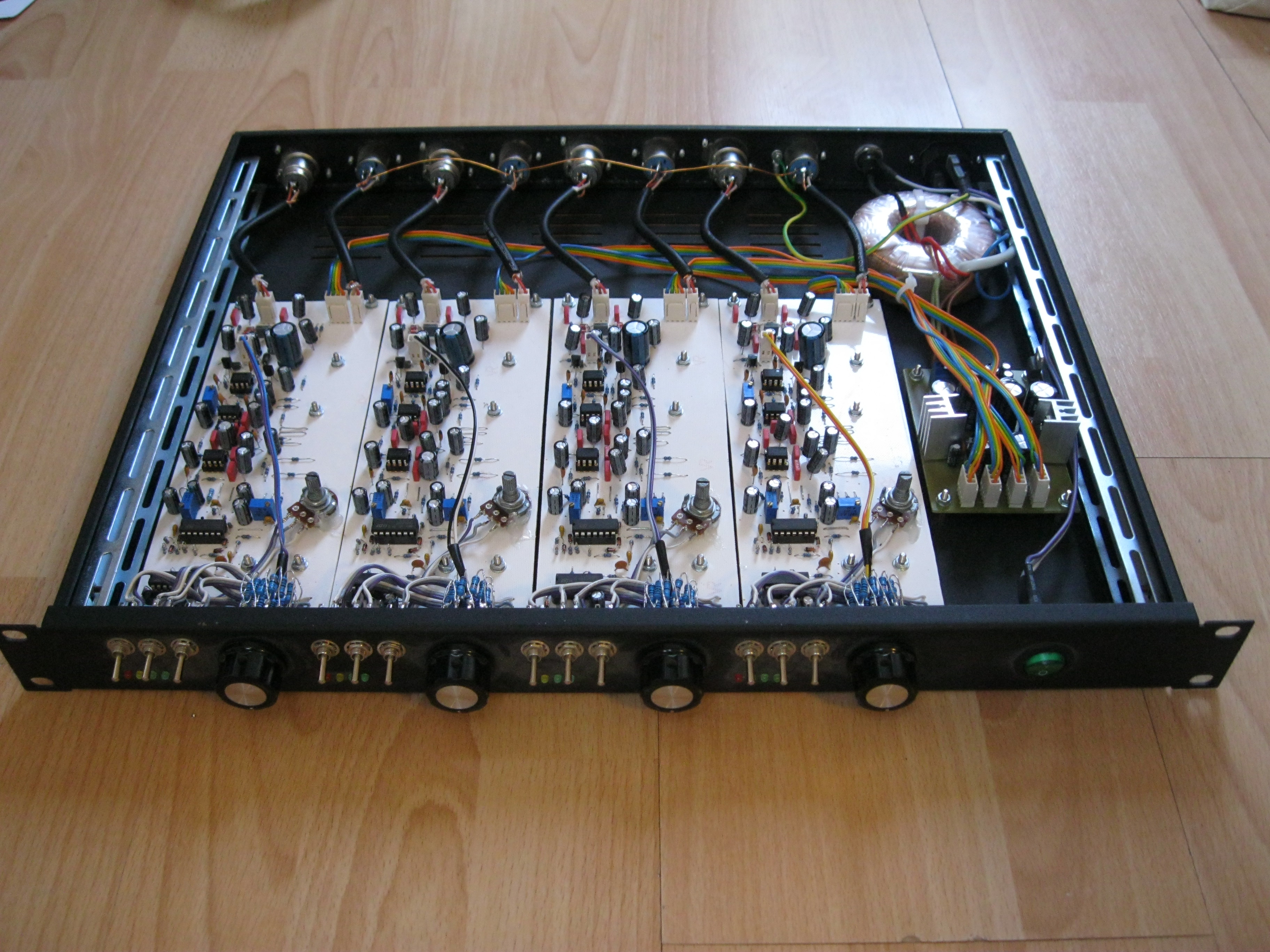
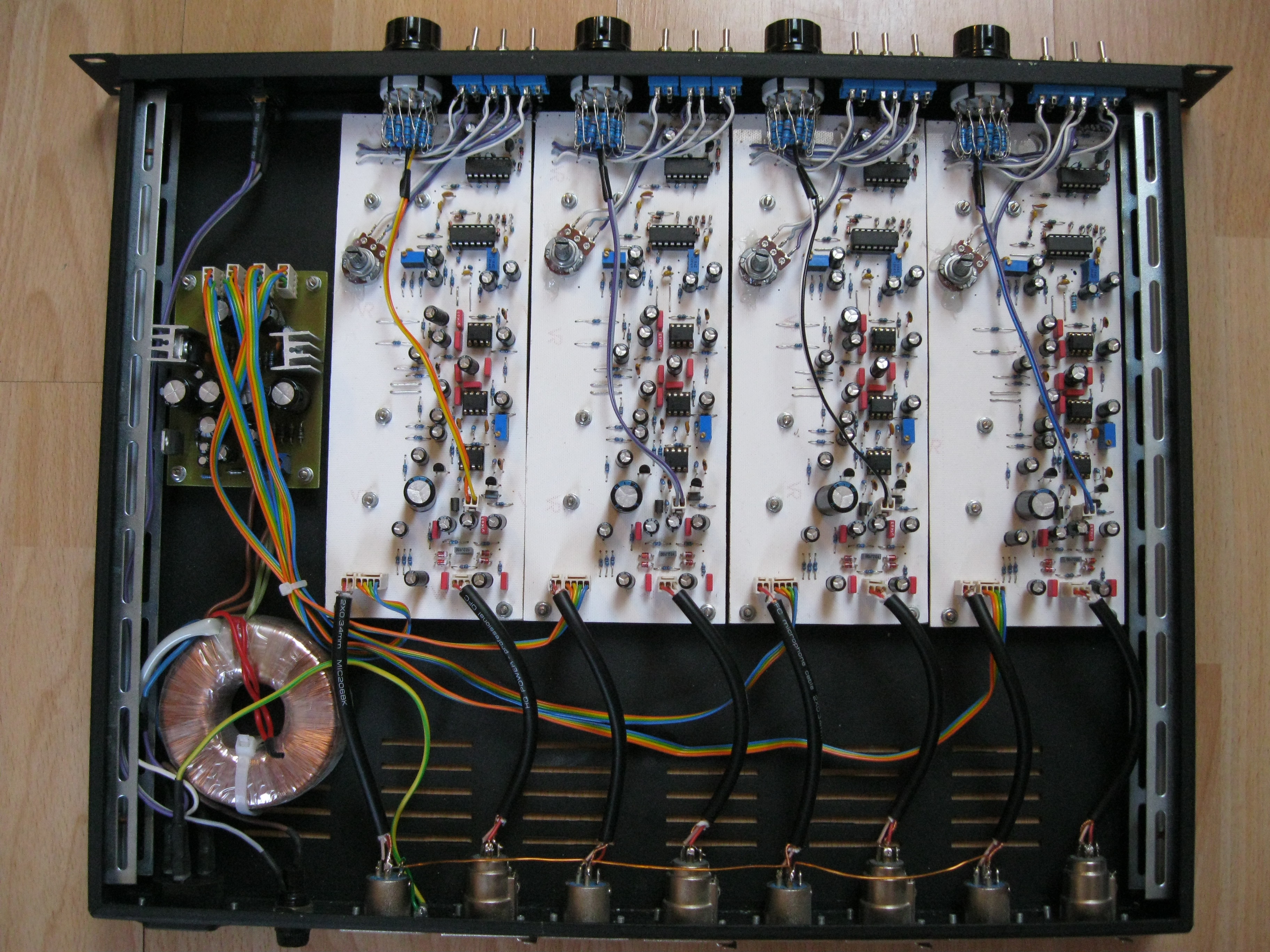

Finally I finished my Green Mic Preamp.
The project is slowly dyeing off, since the source files are hard to obtain.
I plan on making a better simplified SMD version which I will share.

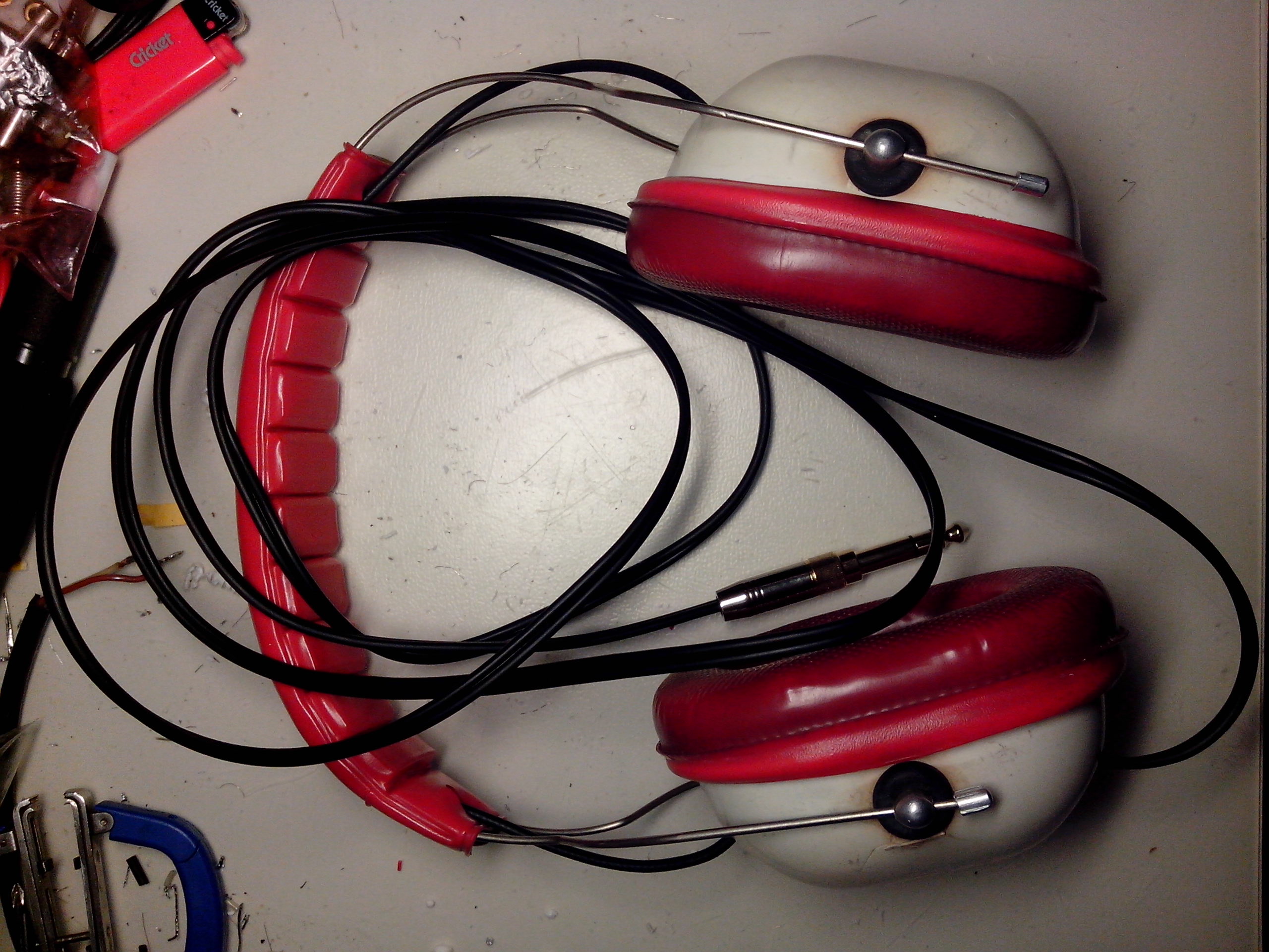
While straying around my favorite on-line auction site, I came across something advertised as headphones. I was in desperate need of monitoring headphones for my studio, so a cheap vintage looking headphones was my choice.
I usually don’t buy unknown stuff, but this seemed a good vintage quality.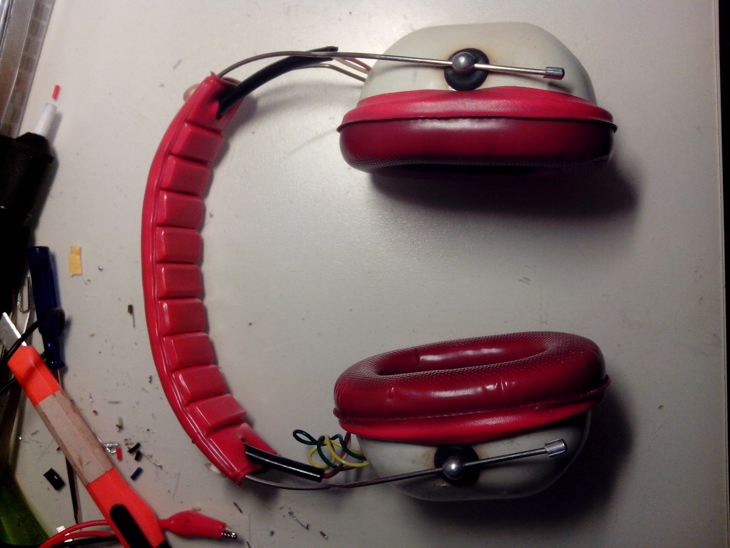
Well to my surprise a pair of DIYed communist ear muffs turned headphones arrived. I was thrilled! I wanted to do this kind of mod for a long time, but never got around to it, and most importantly I love and appreciate DIY electronics, especially old ones from the regime gone by, when it was hard to obtain even the basic parts for building something.
So the first dissection showed a polystyrene fill and most importantly, what has been used for the audio transducer… an old Tesla ARZ 084. It’s a AlNiCo, 84dB 0.25W, 75 Ω, “wide range” (350-4500) speaker. Used in old small germanium transistor radios etc.
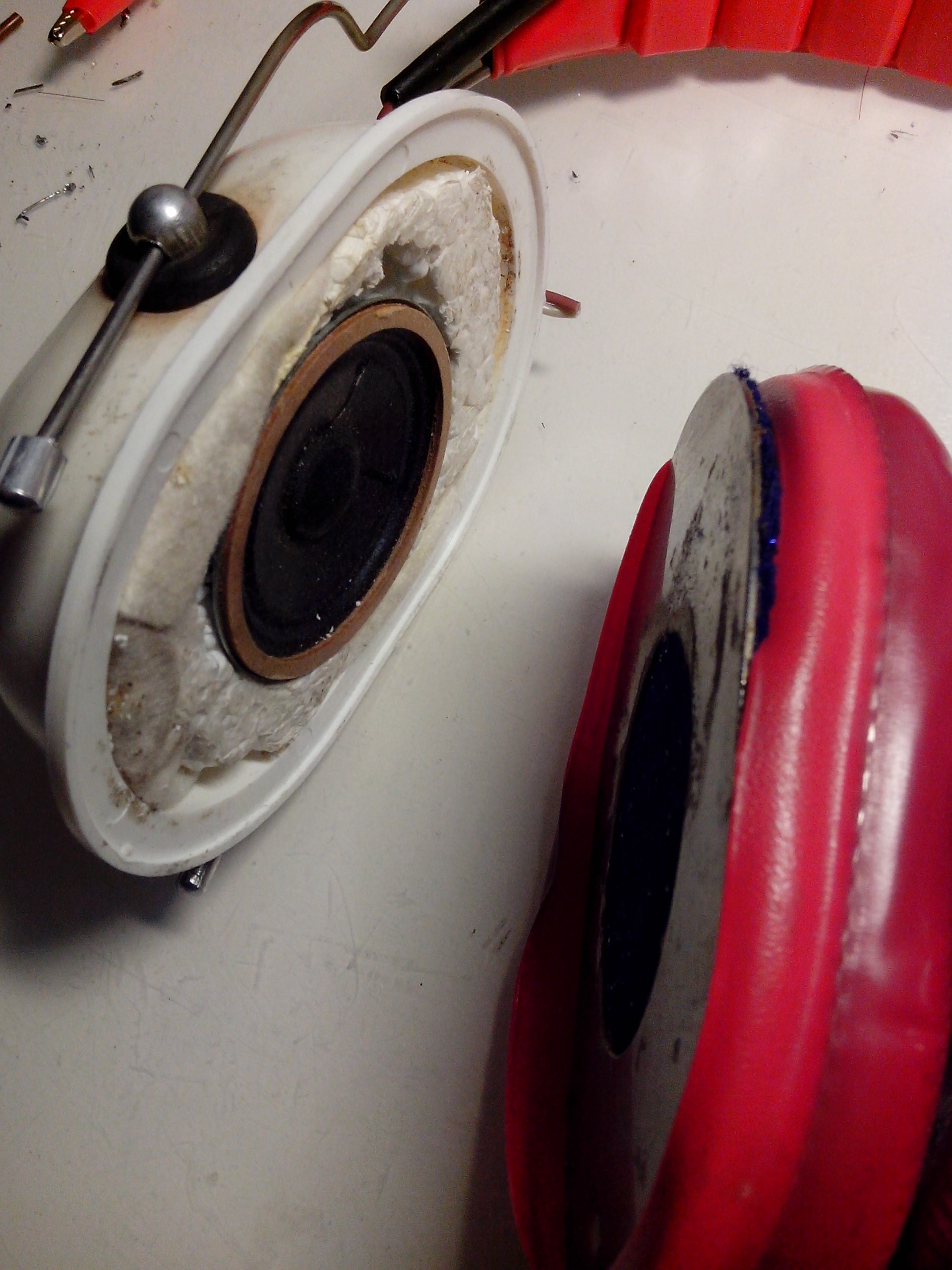
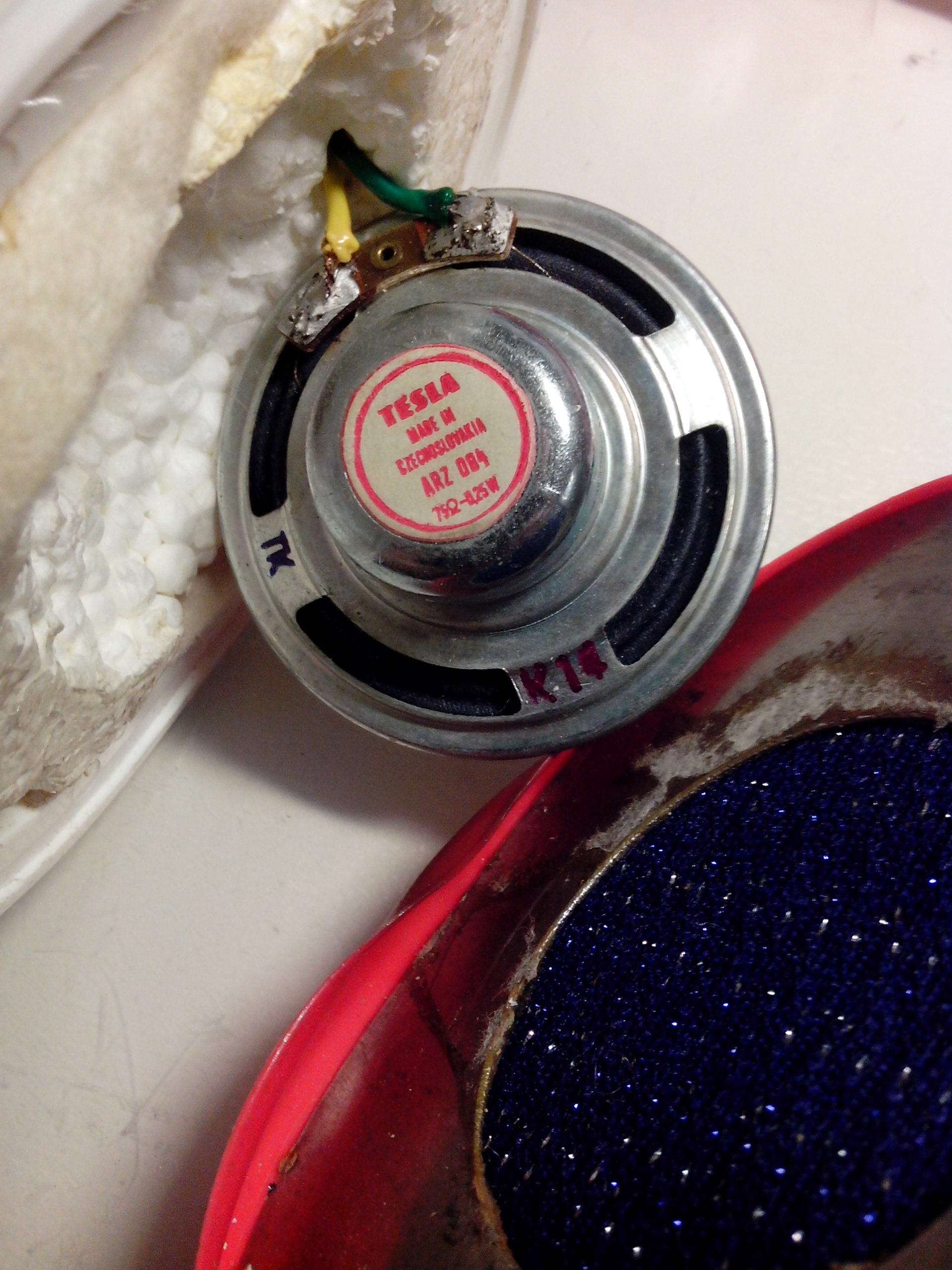
I couldn’t be happier! I chopped the old horrible wires with a DIN-5 connector and startedrefurbishing. I just couldn’t wait how the headphones will sound…
First I opened the headphones and desoldered the speakers.
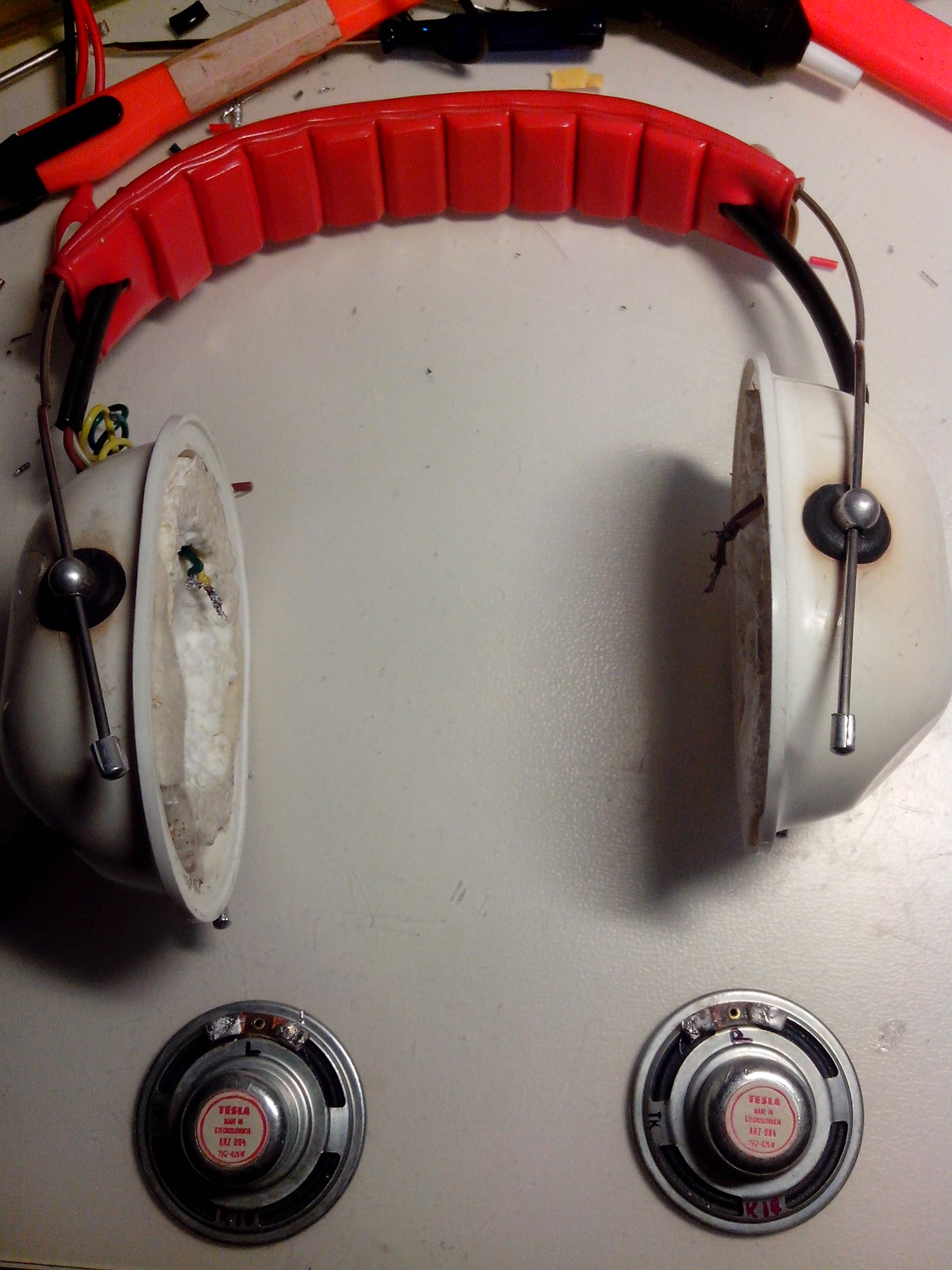
Drilled bigger holes for the rubber reducers for the audio cables. The plastic was cracked around the mounting point…

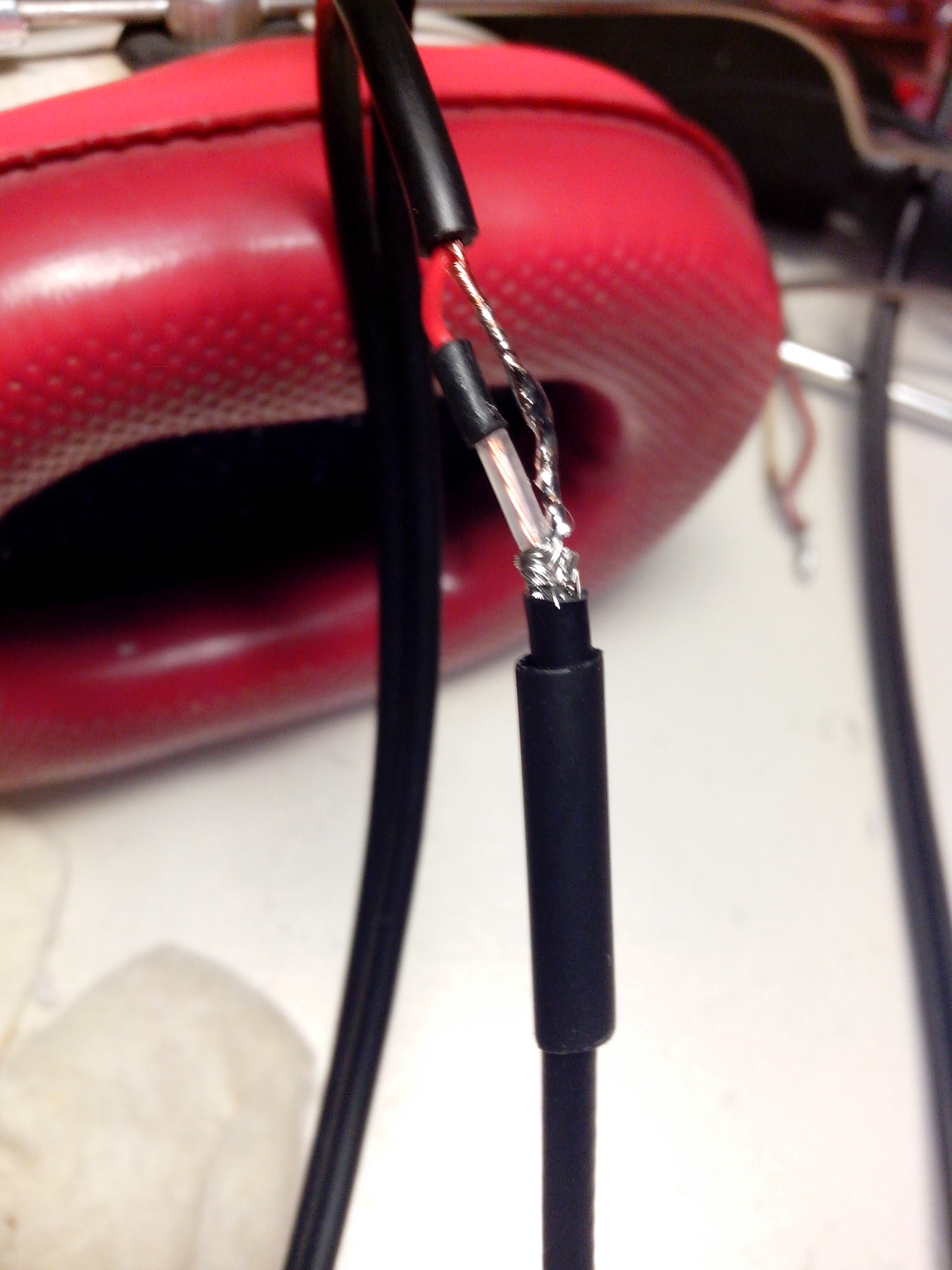
For connecting the two phones I used a small 50 Ohm, very flexible and sturdy coax. I used it in one of my audio amplifiers as well and it proved to be suitable. It is half the price of the standard shielded cable, and after a discussion with my colleges who do HF measurements about the suitability for audio, which they approved and I will continue to use it.
For the rest of the cable connecting headphones to the jack I used a standard 2 meter, shielded stereo cable.
I was pleased with the way everything fallen in place.
For the jack connector I decided on the one I just ordered from china to try out. I must say it is high quality, there is a little problem when you try to unscrew the 6.3 mm jack, you unscrew the whole connector. This can be fixed with a drop of glue or by wear out over time.
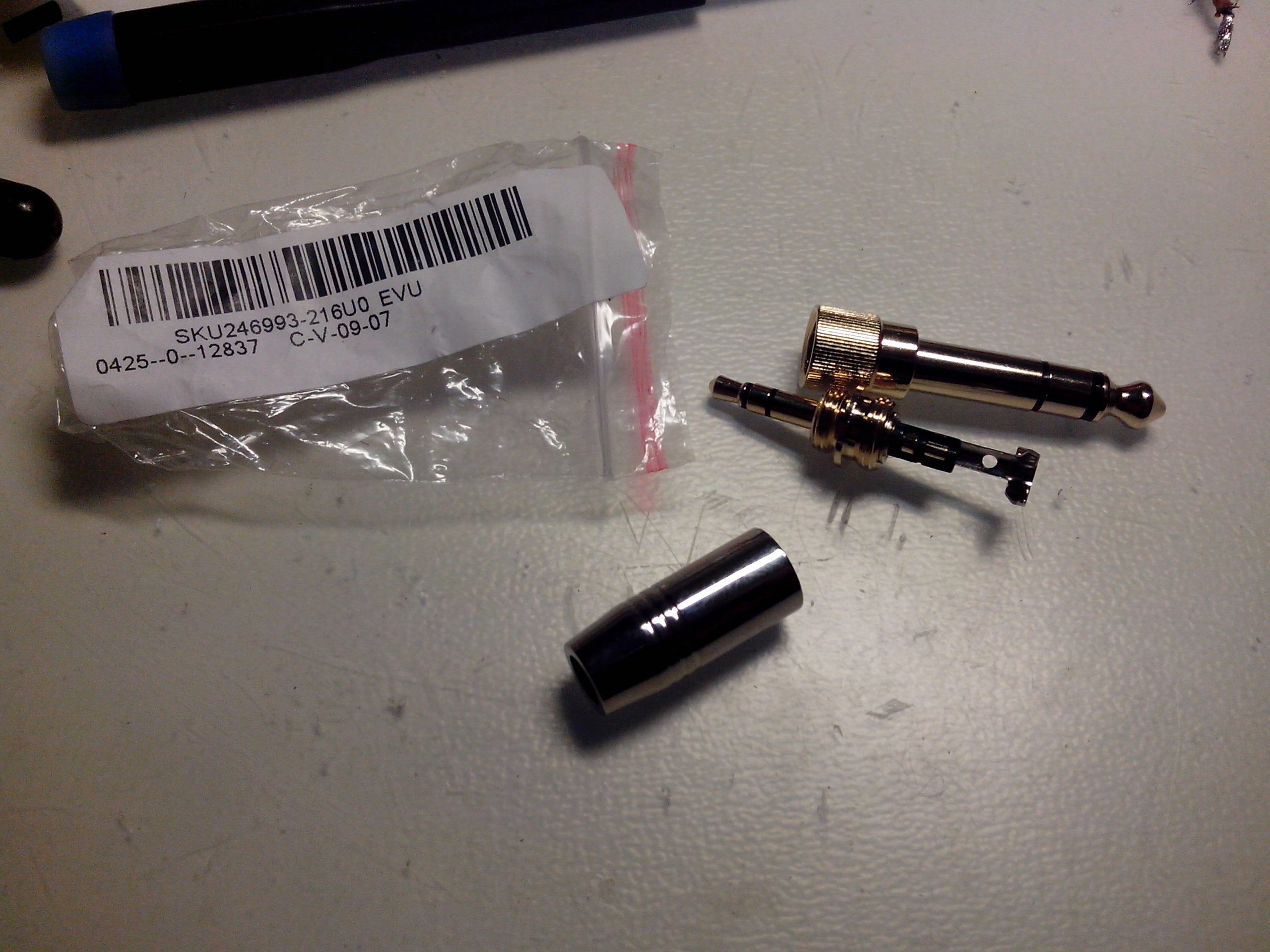
Everything has finally fallen into place. Now to try it out…
I chose Jack White’s Blunderbuss.
Ok, first few seconds quite good, a little too silent when at MAX volume due to speaker impedance I guess…and now the BASS part…
Oh.
What did I expect anyway…No bass in sight. But I am not sad, I will probably upgrade the in the future with something like this.
Anyway, this has been a fun project.
R.
I build this primarily to use with my Tascam DR-40, since it doesn’t have enough gain for dynamic microphones, and it turned out great. I have couple of boards and components bundled together as a kit. Battery not included.
If anyone is interested, drop me a line.
Op-amp is: AD8648 ARUZ
High Gain about 43dB, set by a trimmer.
Balanced input, unbalanced output.
Very simple, mainly for field use. Very low battery consumption below 6mA.
SNR about 94dB
Trimmers are bottom mouneted now.
Green LED to indicate ON/OFF.
The famous Fetboy (Hamptone) Microphone Preamplifier.
Layout updated with 2k multi-turn trimmers to set the working point of the J-FETs. MPSA14 and BD139 used in working prototype.
Layout was made for transformers I had laying around.
Coupling capacitors can be changed to anythin from 10uF-47uF electrolytes. The poly capacitor is really not necessary.
About 26dB of gain.
Set 4V at the 100Ohm resistors (R8, R14) with the 100k trimers (R7, R13). Then set working point using a generator and osciloscope and the 2k trimers (R19, R20).

FETBOY (Hamptone) Microphone Preamp
Eagle 5 files availible for download. Supply PCB for a 24VAC transformer included.
Here is an adaptation of basic Class A MOSFET Headphone amplifier. Below schematic and the board layout. Its designed as a single sided PCB board. It`s always a good idea to use a low ESR coupling capacitor. Also use a ceramic capacitor in the supply and a good heat-sink for the transistors, at least one for a 5 Watt heat dissipation.
Amplifier is for use with pretty common 32 Ohm headphones. For input I used RCA connectors, and for output the preffered 6.35 mm TRS (Tip-Ring-Sleve) Jack!
At the bottom you can find a link for with EAGLE .brd & .sch and an exported .pdf. I will later add a tutorial on exporting your boards from EAGLE, so you can really do all by yourself. For link to EAGLE software go to “Links” section of the site
http://www.sendspace.com/file/4qutiw